 KIO Technology
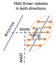 A hexagonal beam is a form of the Yagi antenna which is based on parasitic principles developed early in the last century in Japan for achieving gain in one direction. Alright, so how does a Yagi work then? Well, a two element Yagi has a driver and a reflector made of aluminum tubing that is mounted on a boom and supported by a mast. Basically, the driven element configured as a dipole radiates in both directions broadside to its axis as shown in red. When the RF wave strikes the reflector element, it induces current in the reflector causing it to radiate in both directions also (green).
 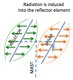 So there are two elements radiating, the driver from energy fed directly from the transmission line and the reflector from induced energy. The energy waves combine with each other for resulting waves in the forward direction and in the reverse direction (blue).
Because of the distance between the driver and the reflector elements the reflector wave combines with the driven wave in the forward direction (right) but subtracts from the driver wave in the reverse direction(left). This causes in the forward direction a resultant stronger wave than either one of them alone. This is how “gain” is achieved in the forward direction. At the same time in the reverse direction, the original wave and the reflected wave tend to cancel each other with a net result of a reduced RF signal. This is how “front/back” discrimination is achieved. 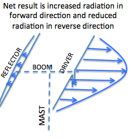 A parasitic beam does not actually generate any new RF energy, it merely results in a focused beam of the original energy fed to the driven element.
A hexagonal beam operates exactly the same way but instead of a driven element that is straight like a dipole, it is a wire bent into the shape of the letter M. The reflector, instead of being straight is also a wire bent into a large U shape. On a hexagonal beam there are six arms extending from the center that form a frame on which the wires of the driver and reflector are supported. Of course, the length of the wires of the driver and reflector must also be the right length for each band which is approximately a half wavelength. The spacing between the ends of the driver wires and the reflector wires also has to be a certain fraction of the wavelength of each frequency band for the best compromise of gain performance and SWR. This spacing is maintained by simply using insulated cord spacer between the tips of the reflector and the driver wires.
The driver wire is broken in the middle where it comes to the center of the hexagonal beam or the bottom of the middle of the “M.” where it is fed by a transmission line from the radio. The result is that you have a wire configuration that performs like a two element Yagi and is directional depending on the aim of the beam.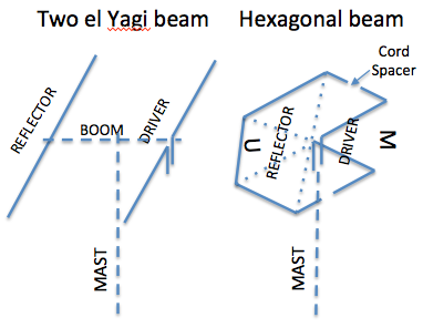
While it is not shown here, because of the fact that the feed point comes back to the middle, it is possible to nest several bands together conveniently. A center post that supports the terminals for each band is mounted vertically in the middle. So what looks like an upside down umbrella frame with an unreal mess of wires, turns out to be a simple two element beam with bent elements and for as many as 6 bands.
